OTA Update Your ESP32 via BLE Without External Libraries - Part 2
In this article series, I will show you how to implement OTA updates via BLE for the ESP32 without external libraries. We will use the NimBLE stack provided by the ESP-IDF for implementing the OTA code. The code is not compatible with the Arduino framework, but the concept is transferable. You can find the complete source code on github and use it as a template for your own projects.
In the first part of this tutorial series we set up the ESP32’s partition table for the OTA process and we reviewed the basics of BLE. In this part we will take a look at the OTA process itself and how we can implement it on the ESP32.
Over-the-Air Update Process
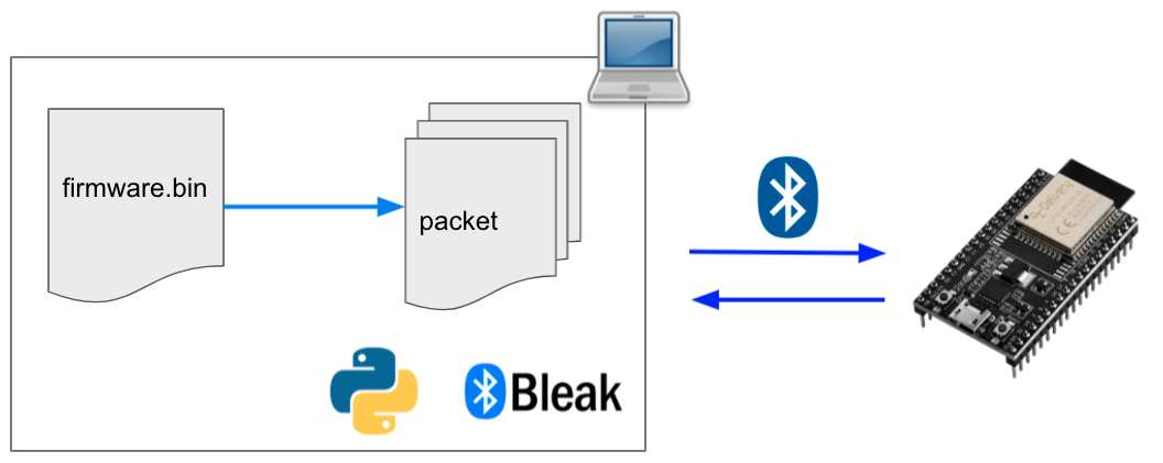
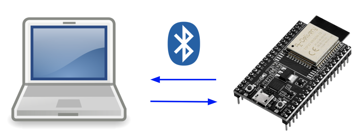
After reviewing the basics, we can talk about the OTA update implementation. The code is separated into two parts: The client implementation on the PC with the Python library Bleak and the server implementation on the ESP32 using NimBLE. The following picture shows a sequence diagram of the OTA process:

During the GAP connection process, the PC and ESP32 negotiate the maximum MTU size. The packet size is calculated based on the MTU size minus 3 bytes for ATT-related overhead. The PC writes the packet size to the OTA Data characteristic. The OTA process kicks off when the PC sends an OTA request to the OTA Control characteristic, to which the ESP32 responds with an acknowledgement.
The Python script splits the firmware binary into packets and consecutively writes them to the OTA Data characteristic. The PC signals that the OTA finished by writing to the OTA Control characteristic, and the ESP32 responds with an acknowledgment notification.
Now we know how the OTA works in general, let us take a look at the implementation in detail.
ESP32 Code
The server-side is implemented using the NimBLE stack. It is the from Espressif recommended way if you are only using BLE. We will create the GATT service table containing all necessary characteristics, set the access flags, and implement access callbacks for each characteristic. These callbacks are pieces of code that NimBLE calls once a client tries to read or write to one of the characteristics.
The ESP32 source code consists of 3 files: main.c, gap.c, and gatt_svr.c. Let’s take a look at each of those files and highlight interesting code snippets!
Main File
The main.c file is the entry point for your code. ESP32 calls the main function when the system boots up. After every boot, we need to check if the currently running firmware boots for the first time. Take a look at this code:
// get the currently running partition
const esp_partition_t *partition = esp_ota_get_running_partition();

// get the state of the currently running partition
const esp_ota_img_states_t ota_state;
esp_ota_get_state_partition(partition, &ota_state);

// check if the state needs verification
// if so an OTA has been done and the app must be checked
if (ota_state == ESP_OTA_IMG_PENDING_VERIFY) {
   ESP_LOGI(LOG_TAG_MAIN, "An OTA update has been detected.");

   if (run_diagnostics()) {
      esp_ota_mark_app_valid_cancel_rollback();
   } else {
      esp_ota_mark_app_invalid_rollback_and_reboot();
   }

}
First, we must check from which partition we are running. With this information, we can retrieve the OTA state. After flashing new firmware, the ESP32 marks the OTA state as ESP_OTA_IMG_NEW. If we boot this image the state changes to ESP_OTA_IMG_PENDING_VERIFY. During the first boot of a new image, we must run a diagnostic check to verify that the new firmware is functional. If the diagnostic runs successfully we can mark the image as ESP_OTA_IMG_VALID. If the diagnostics fail or we reboot the system without setting the image valid, the image will be marked invalid. The bootloader won’t select this image for the next boot and switch back to the old partition (if possible). You can find more information about this rollback process here.
In addition to the verification code, you will also find code to set up the NimBLE stack in the main file. The code is quite self-explanatory and consists of stack initialisation, callback registration, calling the method to initialise the GATT service table, setting the device name, and finally starting the host task for the stack.
GAP
The GAP file implements the code for handling connection events. You can find two callbacks, the GAP event handler, the host task, and the advertisement method here.
Let’s take a look at the two callbacks first: If the NimBLE stack runs into an error and performs a reset, the reset callback will execute. The sync callback fires once the synchronization between the NimBLE host and controller ends. You can read more about that here. What does it mean for us? If the sync happens, the stack is ready and we can start advertising!
The sync callback calls the advertise() function. This function prepares the data to send for the advertisement and starts sending it. The data contains flags that indicate if a client can connect, the transmitted power levels (can be used for distance approximation), the device name, and bits indicating discoverability.
The main piece of code is the GAP event handler. The NimBLE stack calls this function when a GAP event occurs. GAP events include: Connect, disconnect, advertisement complete, subscribe, MTU exchange. You don’t need to modify this code in most cases, but it is valuable to know that you can react to events using this function.
int gap_event_handler(struct ble_gap_event *event, void *arg) {
  switch (event->type) {
    case BLE_GAP_EVENT_CONNECT:
      // A new connection was established
      ESP_LOGI(LOG_TAG_GAP, "GAP: Connection %s: status=%d",
               event->connect.status == 0 ? "established" : "failed",
               event->connect.status);
      break;

    case BLE_GAP_EVENT_DISCONNECT:
      // Connection terminated; resume advertising
      ESP_LOGI(LOG_TAG_GAP, "GAP: Disconnect: reason=%d\n",
               event->disconnect.reason);

      advertise();
      break;

      [...]
  }
The final piece of code in this file is the host task. It simply calls a function to run the NimBLE stack, which will only return if you stop NimBLE manually. Watch the stack size of this task! The task may starve while handling larger BLE packets.
GATT SVR
The file gatt_svr.c contains most of the OTA code: The GATT Service table definition and its associated read / write callbacks. Let us take a look at the service table:
static const struct ble_gatt_svc_def gatt_svr_svcs[] = {
    {
        // service: OTA Service
        .type = BLE_GATT_SVC_TYPE_PRIMARY,
        .uuid = &gatt_svr_svc_ota_uuid.u,
        .characteristics =
            (struct ble_gatt_chr_def[]){
                {
                    // characteristic: OTA Control
                    .uuid = &gatt_svr_chr_ota_control_uuid.u,
                    .access_cb = gatt_svr_chr_ota_control_cb,
                    .flags = BLE_GATT_CHR_F_READ | BLE_GATT_CHR_F_WRITE |
                             BLE_GATT_CHR_F_NOTIFY,
                    .val_handle = &ota_control_val_handle,
                },
                {
                    // characteristic: OTA Data
                    .uuid = &gatt_svr_chr_ota_data_uuid.u,
                    .access_cb = gatt_svr_chr_ota_data_cb,
                    .flags = BLE_GATT_CHR_F_WRITE,
                    .val_handle = &ota_data_val_handle,
                },
                {
                    0,
                }},
    },

    {
        0,
    },
};
This code snippet is the service table for the OTA Service. The first parameter to choose is the type, which is primary in most cases (there are also secondary services, but they are quite rare). The service has a UUID (defined in the header file) and contains two characteristics: OTA Control and OTA Data. The two characteristics are defined similarly: You specify a UUID, an access callback, permission flags, and a value handle. The access callback gets called once a client tries to read or write to the characteristic. The flags specify what operations the client can perform on the characteristics (reading, writing, subscribing to notifications, etc.). The value handle is necessary for sending custom notifications and is used internally by NimBLE to identify the characteristics.
When a client (e.g., the PC) reads or writes to one of the characteristics, the associated access callback fires. It is your responsibility as a developer to implement the callback. Let us take a look at the callback for the OTA Control characteristic:
static int gatt_svr_chr_ota_control_cb(uint16_t conn_handle,
                                       uint16_t attr_handle,
                                       struct ble_gatt_access_ctxt *ctxt,
                                       void *arg) {
  int rc;
  uint8_t length = sizeof(gatt_svr_chr_ota_control_val);

  switch (ctxt->op) {
    case BLE_GATT_ACCESS_OP_READ_CHR:
      // a client is reading the current value of ota control
      rc = os_mbuf_append(ctxt->om, &gatt_svr_chr_ota_control_val, length);
      return rc == 0 ? 0 : BLE_ATT_ERR_INSUFFICIENT_RES;
      break;

    case BLE_GATT_ACCESS_OP_WRITE_CHR:
      // a client is writing a value to ota control
      rc = gatt_svr_chr_write(ctxt->om, 1, length, &gatt_svr_chr_ota_control_val, NULL);
      // update the OTA state with the new value
      update_ota_control(conn_handle);
      return rc;
      break;

    default:
      break;
  }

   [...]
}
We differentiate between reading and writing to the characteristic. You can get this information from the cxtx parameters inherent opcode. If the client reads a value, you must copy the content of the requested variable into the memory buffer om (referenced via cxtx). NimBLE heavily uses these memory buffers for data exchange with the user program (more about them here). The stack takes this buffer and sends the content to the client via BLE. If a client writes to the characteristic, the callback uses the function gatt_svr_chr_write() to unpack the value from the memory buffer and store it in the associated local variable.
Most of this code is boilerplate and not OTA specific. The only OTA-related piece of code is the call of update_ota_control() during the write access. This function checks the received value and starts (or finishes) the OTA process. Let us take a look at the code responsible for starting the OTA:
// OTA request
ESP_LOGI(LOG_TAG_GATT_SVR, "OTA has been requested via BLE.");

// get the next OTA partition
update_partition = esp_ota_get_next_update_partition(NULL);

// start the ota update
err = esp_ota_begin(update_partition, OTA_WITH_SEQUENTIAL_WRITES, &update_handle);

[...]

// retrieve the packet size from OTA data
packet_size = (gatt_svr_chr_ota_data_val[1] << 8) + gatt_svr_chr_ota_data_val[0];
ESP_LOGI(LOG_TAG_GATT_SVR, "Packet size is: %d", packet_size);

// notify the client via BLE that the OTA has been acknowledged (or not)
om = ble_hs_mbuf_from_flat(&gatt_svr_chr_ota_control_val, sizeof(gatt_svr_chr_ota_control_val));
ble_gattc_notify_custom(conn_handle, ota_control_val_handle, om);
ESP_LOGI(LOG_TAG_GATT_SVR, "OTA request acknowledgement has been sent.");

[...]
First, we retrieve the target partition to which we will write the received packets. We start the OTA process by calling esp_ota_begin(). Calling this method tells the ESP32 to prepare for the OTA. The function provides us with an update handle. During the update, we will use this handle for sequentially writing the received packets to the partition. Recall, that the client writes the size of the packets to the OTA Data characteristic. We get the packet size by reading and combining the first two bytes of the received array. Finally, the function sends a notification to the client, letting it know that the OTA is acknowledged (or not).
The OTA Data characteristic has its own callback. The function checks if the update process is started and if so it writes all received packets to the partition with:
esp_ota_write(update_handle, (const void *)gatt_svr_chr_ota_data_val, packet_size);
After transferring all packets, the PC will write to the OTA Control characteristic indicating completion of the OTA. In response, the ESP32 executes the following code:
// end the OTA and start validation
err = esp_ota_end(update_handle);
if (err != ESP_OK) {
   // an error happened during the update
   if (err == ESP_ERR_OTA_VALIDATE_FAILED) {
      // the received firmware is corrupted
      ESP_LOGE(LOG_TAG_GATT_SVR,
               "Image validation failed, image is corrupted!");
   } else {
      // a different error happened; print the error
      ESP_LOGE(LOG_TAG_GATT_SVR, "esp_ota_end failed (%s)!",
               esp_err_to_name(err));
   }
} else {
   // select the new partition for the next boot
   err = esp_ota_set_boot_partition(update_partition);
   if (err != ESP_OK) {
      // the new boot partition could not be selected
      ESP_LOGE(LOG_TAG_GATT_SVR, "esp_ota_set_boot_partition failed (%s)!",
               esp_err_to_name(err));
   }
}

// set the control value
if (err != ESP_OK) {
   // if errors happened set OTA control to DONE NOT ACKNOWLEDGED
   gatt_svr_chr_ota_control_val = SVR_CHR_OTA_CONTROL_DONE_NAK;
} else {
   // if no errors happened set OTA control to DONE ACKNOWLEDGED
   gatt_svr_chr_ota_control_val = SVR_CHR_OTA_CONTROL_DONE_ACK;
}

// notify the client via BLE that DONE has been acknowledged
om = ble_hs_mbuf_from_flat(&gatt_svr_chr_ota_control_val,
                           sizeof(gatt_svr_chr_ota_control_val));
ble_gattc_notify_custom(conn_handle, ota_control_val_handle, om);
ESP_LOGI(LOG_TAG_GATT_SVR, "OTA DONE acknowledgement has been sent.");

[...]
esp_restart();
The function esp_ota_end() completes the OTA by verifying the integrity of the newly written partition. If the verification passes, the bootloader selects this partition for booting in the next reboot (with the state ESP_OTA_IMG_PENDING_VERIFY). The result of the verification process gets send via notification to the client and the ESP32 reboots.
Summary
In this tutorial we implemented the OTA update process on the ESP32: We created a service table containing two characteristics for the OTA, implemented callbacks to react to reads and writes to this characteristics, and wrote the OTA logic itself. In the next part we will implement the OTA code of the client side using Python.
Parts
- OTA Update Your ESP32 via BLE Without External Libraries - Part 1
- OTA Update Your ESP32 via BLE Without External Libraries - Part 2
- OTA Update Your ESP32 via BLE Without External Libraries - Part 3