Zephyr Basics: GPIO
Zephyr, the new real-time operating system everyone is talking about. The relatively young OS was first released in late 2017 and became the most actively developed embedded OS (on GitHub) in 2020. Zephyr is based on Rocket OS, made by Wind River Systems (the guys and girls whose other OS is running on the Mars rover).
The project is hosted with the Linux Foundation and has supporters such as Intel, NXP, Nordic, and Texas Instruments. Zephyr is a modular operating system that includes cooperative and preemptive threading, static memory allocation, a device driver interface, memory protection, a network stack, Bluetooth Low Energy support, USB, Device Firmware Updates, and much more.
I am planing a series of blog posts on Zephyr. Each post will introduce a feature of Zephyr and an example application. In this post, we will take a look at the GPIO (general-purpose input/output) API. We start with blinking an LED by directly writing to an output pin. Afterward, we will integrate this LED into devicetree, Zephyrs hardware abstraction layer. This will allow us to rewrite our blinking program in a more hardware-independent form. After that, we will take a look at inputs by reading the current state of a pushbutton.
How to get Zephyr
Perhaps the easiest way of trying out Zephyr is with our beloved ESP32. Espressif recently announced that they now officially support Zephyr as an alternative to FreeRTOS. This post contains a table with features of Zephyr that are currently supported and features Espressif plans to implement soon. I have been testing Zephyr on ESP32 for a couple of weeks now. I am impressed with how well it works on the inexpensive chip already. Check the list of supported features and give it a try!
To install Zephyr on the ESP32, follow the getting started guide first. After setting up the toolchain, follow this guide to install the ESP32 specific modules and libraries. I am using the ESP32 Dev Kit C4 for this tutorial. It will also work with other boards, but you may need to change the pins.
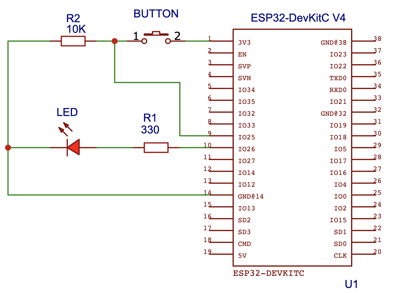
To try the examples from this blog post, you need an LED with a resistor in series and a pushbutton with a pull-down resistor. Please connect the parts to your ESP32 as shown on the following schematic:
Blinking an LED - Hello Zephyr
Let us begin with the “Hello World” of embedded systems: Blinking an LED. The following code will make the LED connected to pin 26 of your ESP32 blink:
#include <zephyr.h>
#include <device.h>
#include <drivers/gpio.h>

#define LED_PIN 26

void main(void) {
  // get the GPIO device
  const struct device * dev = device_get_binding("GPIO_0");
  // configure the LED pin as output
  gpio_pin_configure(dev, LED_PIN, GPIO_OUTPUT);

  // loop forever
  while (1) {
    gpio_pin_toggle(dev, LED_PIN);
    k_msleep(1000);
  }
}
What is going on here? If you are coming from Arduino, you might be wondering what a device is or what device_get_binding does? Zephyr uses a concept called devicetree for hardware abstraction, a data structure describing the hardware of an embedded system. The concept is borrowed from the Linux kernel.
What is devicetree?
Devicetree allows you to decouple your higher-level application code from the hardware components used in your embedded systems. This is an extremely powerful feature! Imagine you build a system that needs an inertial measurement unit (IMU): You do your research, find a suitable chip, and integrate it into your system. After some months, you find out that this chip is no longer available or the price became too high (we live in a global chip shortage after all!). Luckily, you are prepared for this! You abstracted the driver implementation for the two chips with devicetree. Your application code only ever uses the chip’s functionality via a device-independent API. This makes it easy to use a new chip with a new driver implementation. You only need to change the configuration files, to enable your application to use the new chip. We will take a deeper dive into devicetrees in a future blog post!
Accessing the GPIO Device
Using the function device_get_binding(“GPIO_0”) we gain access to a struct representing the GPIO hardware. The implementation details remain encapsulated in the driver’s implementation (e.g.: how the gpios map to the processors’ registers). You can run this program with very little change on any microcontroller supporting Zephyr, not only the ESP32.
The GPIO API provides two useful functions for us: Before we can use a pin as an output for the LED, we need to set it as an output using gpio_pin_configure(). The second function gpio_pin_toggle() enables us to blink the led: Calling it changes the pin’s state from high to low or low to high, thus making the LED blink.
Take these two functions, add an infinite loop and a delay (k_msleep()) - et voilà you got yourself a working blinky program!
Adding the LED to Devicetree
That was easy enough! Now we know how to set the state of a pin directly. In the next step, we will add the LED as a device to devicetree. The easiest way to do this is with an overlay. You can think of this as a patch file for the devicetree. It allows you to add your own devices, overwrite existing ones, or specify aliases. In your project’s root folder, create a file called esp32.overlay with the following content:
/ {
	leds {
		compatible = "gpio-leds";
		led0: led_0 {
			gpios = <&gpio0 26 GPIO_ACTIVE_HIGH>;
		};
	};
};
Once you hit compile, West (Zephyr’s build/flash/… tool) will take your overlay and patch it into the ESP32 devicetree. This will create a new node called leds directly under the root node (the root node is named /). It contains a special property called compatible. It typically contains the vendor and name of a device. For LEDs the vendor does not matter, the value is set to the generic gpio-leds.
The node leds contains a single child node called led_0, this is the actual device specification of the LED. Do not be confused by the two names: led_0 is the name of the node and led0 is the label of the node. The node contains one property: With gpios you can set the GPIO device (or bank) to use, the pin, and flags for configuration. Our LED is connected to pin 26 of the GPIO device (or bank) gpio0 and the flag is set to be active high (the output pin is high, when active).
Now you can rewrite your application to use your LED device:
#include <zephyr.h>
#include <device.h>
#include <drivers/gpio.h>

#define LED0_NODE DT_NODELABEL(led0)
#define LED_GPIO DT_GPIO_LABEL(LED0_NODE, gpios)
#define LED_PIN DT_GPIO_PIN(LED0_NODE, gpios)
#define LED_FLAGS DT_GPIO_FLAGS(LED0_NODE, gpios)

void main(void) {
  // get the GPIO device
  const struct device * dev = device_get_binding(LED_GPIO);
  // configure the LED pin as output
  gpio_pin_configure(dev, LED_PIN, GPIO_OUTPUT | LED_FLAGS);

  // loop forever
  while (1) {
    gpio_pin_toggle(dev, LED_PIN);
    k_msleep(1000);
  }
}
As you can see the number of the output pin is not in the program anymore! Great, but now we have 4 new defines!? What is going on? These defines are used to extract information from the devicetree. First, we need to get the node identifier of the LED device. This can be done easily with the macro DT_NODELABEL, we just pass it the label of our device (led0). Using the LED’s node identifier and further devicetree macros, we can extract the GPIO device, the pin, and the flags.
At this point you might be thinking: Why do I need all this to blink an LED? You don’t, but with this simple example you can already see one of the main selling points of devicetree: You abstracted the hardware details and only work with aliases. There is no need to know at which pin the LED is connected, what GPIO device it uses, or which additional setup flags it needs.
Reacting on a Button Press
Let’s leave the devicetree world for a moment and go back to simpler GPIO! We know now how to handle outputs with Zephyr, but how do we work with inputs? How can we read the current state of the pushbutton connected to the ESP32?
The pushbutton has only two possible states: If not pressed, the input pin reads 0. If pressed, the connection to +3.3V is closed, the input pin reads 1. The following program reads the current state of the button. If the button gets pressed, the LED lights up. If you press it again, the LED will turn off.
#include <zephyr.h>
#include <device.h>
#include <drivers/gpio.h>

#define LED_PIN 26
#define BUTTON_PIN 25

#define DEBOUNCE_TIMEOUT_MS 50

void main(void) {
  uint64_t t0 = 0, now = 0;
  uint8_t state = 0, current_state = 0, last_state = 0;

  // get the GPIO device
  const struct device * dev = device_get_binding("GPIO_0");

  // configure the button pin as input
  gpio_pin_configure(dev, BUTTON_PIN, GPIO_INPUT);
  // configure the LED pin as output
  gpio_pin_configure(dev, LED_PIN, GPIO_OUTPUT);

  // loop forever
  while (1) {
    // if the button state changes, store the time
    current_state = gpio_pin_get(dev, BUTTON_PIN);
    if (current_state != last_state) {
      t0 = k_uptime_get();
    }
    last_state = current_state;

    // check if the debounce timeout is over
    now = k_uptime_get();
    if ((now - t0) < DEBOUNCE_TIMEOUT_MS) {
      continue;
    }

    // if the button is pressed, toggle the LED
    if (state != current_state) {
      state = current_state;
      if (current_state == 1) {
        gpio_pin_toggle(dev, LED_PIN);
      }
    }
  }
}
Pushbuttons tend to bounce when pressed. This means that a single press of the button may be read as a series of presses. To takle this we need a simple debouncing mechanism. We will only consider a button pressed, if the input reads high for more than 50ms. You may need to increase this time depending on your setup.
In the main loop we continuously read the state of the button. The current and previously read state is stored in each iteration. If the state changes due to a button press or release, we store the current system uptime in the variable t0. In each iteration t0 is compared to the current uptime. If the difference is less than 50ms, we skip to the next iteration of the loop. If the difference is larger than 50 ms, it means the state of the button is stable and the bouncing phase is over. After this guard condition, we can savely toggle the LED. Remember, we only toggle the LED on a button press, meaning the state changes from 0 to 1.
Adding the Button to Devicetree
You already knew what was coming next. Let us add the button to devicetree! Here is our final esp32.overlay file and the new code:
/ {
	leds {
		compatible = "gpio-leds";
		led0: led_0 {
			gpios = <&gpio0 26 GPIO_ACTIVE_HIGH>;
		};
	};

	buttons {
		compatible = "gpio-keys";
		button0: button_0 {
			gpios = <&gpio0 25 GPIO_ACTIVE_HIGH>;
			label = "Button";
		};
	};
};
#include <zephyr.h>
#include <device.h>
#include <drivers/gpio.h>

#define SW0 DT_NODELABEL(button0)
#define LED0 DT_NODELABEL(led0)

#define DEBOUNCE_TIMEOUT_MS 50

static
const struct gpio_dt_spec button = GPIO_DT_SPEC_GET(SW0, gpios);
static
const struct gpio_dt_spec led = GPIO_DT_SPEC_GET(LED0, gpios);

uint64_t last_time = 0;
struct gpio_callback button_cb_data;

void button_callback(const struct device *dev,
	struct gpio_callback *cb, uint32_t pins)
{
  uint64_t now = k_uptime_get();
  if ((now - last_time) > DEBOUNCE_TIMEOUT_MS)
  {
    gpio_pin_toggle_dt(&led);
  }
  last_time = now;
}

void main(void)
{
  // make sure the GPIO device is ready
  if (!device_is_ready(button.port))
    return;

  // configure the LED pin as output
  gpio_pin_configure_dt(&led, GPIO_OUTPUT);

  // configure the button pin as input
  gpio_pin_configure_dt(&button, GPIO_INPUT);
  // configure the interrupt on button press (pin goes from low to high)
  gpio_pin_interrupt_configure_dt(&button, GPIO_INT_EDGE_TO_ACTIVE);

  // setup the button press callback
  gpio_init_callback(&button_cb_data, button_callback, BIT(button.pin));
  gpio_add_callback(button.port, &button_cb_data);
}
Let’s go through the code! We start by fetching the node identifiers for the LED and the button using the macro DT_NODELABEL. We are using a different approach for obtaining the GPIO information from devicetree: With the identifiers, we query the GPIO specifications directly using the macro GPIO_DT_SPEC_GET. The specs struct contains all the needed information from the devicetree: The GPIO device (.port), the pin (.pin), and the flags (.dt_flags). There is no need to query them separately.
The caveat to this approach is that, before we use the devices, we need to check if they are ready first. This is done in the first line of the main loop (don’t forget to implement the error case in production code!). The LED and the button use the same GPIO device, it is sufficient to only check one of them.
After we made sure that the device is ready, we configure the LED as output and the button as an input. Keep in mind that by using the specs, you need to call different functions than before (and pass the specs struct by reference)! Additionally, we configure an interrupt for the button, which fires once the button state changes from inactive (0) to active (1).
Notice that we don’t use a loop anymore! Zephyr allows you to add a callback to your GPIOs. Every time you press the button, this callback gets executed. The logic to toggle the LED is implemented inside this callback function (called button_callback in our case). The last two lines of our main function initialize the callback and connect it to the button pin.
Notice that we don’t use a loop anymore! Zephyr allows you to add a callback to your GPIOs. The last two lines of our main function initialize the callback and connect it with the button pin. Every time you press the button, this callback gets executed. The logic to toggle the LED is inside this callback function (called button_callback in our case). Zephyr supports a flag for pin debouncing but is not implemented for the ESP32 yet. That is why we still need to add code for debouncing: On each call, we check how much time passed since the last press. If more than 50ms passed, we toggle the LED.
Summary
In this blog post, we talked about Zephyrs GPIO API. We started with the Hello World of embedded systems: Blinking an LED. We quickly got into contact with devicetree, Zephyr’s way of hardware abstraction. We learned how to add an LED and a button to devicetree and use them in our program.
I hope this post helped you to understand Zephyr a little better. I will post more tutorials soon. There is a lot to learn about the new real-time operating system everyone is talking about.
References
- https://www.zephyrproject.org/
- https://docs.zephyrproject.org/latest/reference/peripherals/gpio.html
- https://docs.zephyrproject.org/latest/guides/dts/index.html
- https://github.com/zephyrproject-rtos/zephyr/tree/main/samples/basic/blinky
- https://github.com/zephyrproject-rtos/zephyr/tree/main/samples/basic/button