Zephyr Basics: Shell
Welcome back to Zephyr basics! In this blog post, we will take a look at Zephy’s Shell, one of the most useful features for debugging and maintenance. The shell is similar to the ones you know from Unix/Linux. It can be accessed via the UART port and comes with various built-in features. Out of the box, you can use it to change parameters, set/read GPIOs, access the I2C bus, change log levels, and more. In this tutorial, we will take a look at how to set up the shell, the built-in commands, and how to implement a custom shell command. You can find the full source code on GitHub.
Built-in Commands
Let’s dive right in! To activate the shell you need to add the following to your prj.conf:
prj.conf:
CONFIG_SHELL=y
There are many ways to connect with the shell: You can use the tool screen, putty, west’s extension for ESP32, or any other remote terminal solution you like.
My ESP32 is recognised as /dev/tty.usbserial-0001, using the tool screen I connect to it via:
$ screen /dev/tty.usbserial-0001 115200
This will open the connection to the Zephyr shell. Let’s try our first command: Asking for help.
uart:~$ help
Please press the <Tab> button to see all available commands.
You can also use the <Tab> button to prompt or auto-complete all commands or its subcommands.
You can try to call commands with <-h> or <--help> parameter for more information.
Shell supports following meta-keys:
  Ctrl + (a key from: abcdefklnpuw)
  Alt  + (a key from: bf)
Please refer to shell documentation for more details.
Available commands:
  clear     :Clear screen.
  device    :Device commands
  devmem    :Read/write physical memory
             Usage:
             Read memory at address with optional width:
             devmem address [width]
             Write memory at address with mandatory width and value:
             devmem address <width> <value>
  help      :Prints the help message.
  history   :Command history.
  i2c       :I2C commands
  kernel    :Kernel commands
  led_ctrl  :Command to change LED states.
  resize    :Console gets terminal screen size or assumes default in case the
             readout fails. It must be executed after each terminal width change
             to ensure correct text display.
  shell     :Useful, not Unix-like shell commands.
uart:~$
In the output you can see various available commands and a small description for them. Don’t worry if you don’t see the command led_ctrl yet, it is the one we are going to implement in this tutorial.
Let us try out some kernel commands: Write kernel and press Tab on your keyboard:
uart:~$ kernel
  cycles   stacks   threads  uptime   version  sleep
uart:~$
You will see all available subcommands for the kernel. If you want to know more about them, you can use the subcommand help:
uart:~$ kernel help
kernel - Kernel commands
Subcommands:
  cycles   :Kernel cycles.
  stacks   :List threads stack usage.
  threads  :List kernel threads.
  uptime   :Kernel uptime.
  version  :Kernel version.
  sleep    :ms
uart:~$
With the following command, Zephyr prints the currently running threads:
uart:~$ kernel threads
Scheduler: 6804 since last call
Threads:
 0x3ffb0628 sysworkq
        options: 0x0, priority: -1 timeout: 0
        state: pending, entry: 0x40082e74
        stack size 1024, unused 716, usage 308 / 1024 (30 %)

*0x3ffb0458 shell_uart
        options: 0x0, priority: 14 timeout: 0
        state: queued, entry: 0x400d2724
        stack size 2048, unused 524, usage 1524 / 2048 (74 %)

 0x3ffb04f0 idle
        options: 0x1, priority: 15 timeout: 0
        state: , entry: 0x40081d88
        stack size 1024, unused 828, usage 196 / 1024 (19 %)

 0x3ffb0588 main
        options: 0x1, priority: 0 timeout: 10001
        state: suspended, entry: 0x400818a0
        stack size 2048, unused 1504, usage 544 / 2048 (26 %)

uart:~$
Play around with the system commands for a while, and check out all the other options you can find. Many Zephyr modules provide Shell support, but you must first activate it in the prj.conf. This option is often not well documented and needs a bit of digging in the documentation. Let’s check out one of the modules’ shell extensions, the I2C shell.
Accessing the I2C Bus
A tremendously useful feature of the Zephyr shell is, that you can directly interact with the I2C bus. I have an MPR121 capacitive touch sensor connected to the I2C bus, let us try to read something from it.
First, we need to activate the feature in our prj.conf:
prj.conf:
CONFIG_I2C=y

CONFIG_SHELL=y
CONFIG_I2C_SHELL=y
Then, we need to get the address of the I2C bus device, which you can get with the following command:
uart:~$ device list
devices:

- rtc@3ff48000 (READY)
- gpio@3ff44800 (READY)
- gpio@3ff44000 (READY)
- uart@3ff40000 (READY)
  requires: rtc@3ff48000
- i2c@3ff53000 (READY)
  requires: rtc@3ff48000
  requires: gpio@3ff44000
With the address, we can scan the bus and print a table with all available I2C devices:
uart:~$ i2c scan i2c@3ff53000
0 1 2 3 4 5 6 7 8 9 a b c d e f
00: -- -- -- -- -- -- -- -- -- -- -- --
10: -- -- -- -- -- -- -- -- -- -- -- -- -- -- -- --
20: -- -- -- -- -- -- -- -- -- -- -- -- -- -- -- --
30: -- -- -- -- -- -- -- -- -- -- -- -- -- -- -- --
40: -- -- -- -- -- -- -- -- -- -- -- -- -- -- -- --
50: -- -- -- -- -- -- -- -- -- -- 5a -- -- -- -- --
60: -- -- -- -- -- -- -- -- -- -- -- -- -- -- -- --
70: -- -- -- -- -- -- -- --
1 devices found on i2c@3ff53000
Zephyr found a device on address 0x5a, which is the default address of the MPR121 controller.
Now, that we have detected the device on our bus let’s read something from it. Checking the datasheet you will find out that the register 0x5d contains the default value 0x24 after a reset. Let’s verify that:
uart:~$ i2c read_byte i2c@3ff53000 0x5a 0x5d
Output: 0x24
It worked!
I hope you can see now how useful the Zephyr shell can be for rapid prototyping, debugging, and configuring your system. But you don’t need to stop with the built-in commands! Let’s have a look at how you can create your own commands and expand the shell’s functionality yourself.
How to Create a Custom Shell Command
Let us create our own shell command! In this example, we will create a command to control a traffic light consisting of 3 LEDs. We will implement subcommands to turn LEDs on / off, and make them blink.
Setup
To prepare yourself for the tutorial, connect three LEDs (and resistors) to your ESP32: A green LED to pin 25, a yellow LED to pin 26, and a red LED to pin 27.
Set up the LEDs similarly to my post about GPIOs. Create the following two files in the root folder of your project:
esp32.overlay:
/ {
	leds {
		compatible = "gpio-leds";
		ledgreen: led_g {
			gpios = <&gpio0 25 GPIO_ACTIVE_HIGH>;
		};
		ledyellow: led_y {
			gpios = <&gpio0 26 GPIO_ACTIVE_HIGH>;
		};
		ledred: led_r {
			gpios = <&gpio0 27 GPIO_ACTIVE_HIGH>;
		};
	};
};
prj.conf:
CONFIG_GPIO=y
CONFIG_SHELL=y
With the devicetree overlay, we can reference the LEDs in our program by name instead of hard coding the pin number.
Controlling the LEDs
Our program is split roughly into two parts: The macros to generate the custom shell commands and the functions to control the LEDs. Let us first take a look at how the LEDs are controlled:
An LED can be abstracted with the following struct:
enum LED_STATE { LED_OFF, LED_ON, LED_BLINKING };

struct led {
  const struct gpio_dt_spec device;
  enum LED_STATE target_state;
};
It contains the device tree device for the LED and a target state. The target state will be set by the shell commands and executed by our main function. Using this struct we can create 3 instances for our LEDS:
static struct led led_green = {
    .device = GPIO_DT_SPEC_GET(DT_NODELABEL(ledgreen), gpios),
    .target_state = LED_OFF,
};

static struct led led_yellow = {
    .device = GPIO_DT_SPEC_GET(DT_NODELABEL(ledyellow), gpios),
    .target_state = LED_OFF,
};

static struct led led_red = {
    .device = GPIO_DT_SPEC_GET(DT_NODELABEL(ledred), gpios),
    .target_state = LED_OFF,
};
In the main function, we first assert that the GPIO device (the GPIO bank our LEDs are connected to) is ready. Do not forget to handle the error case in production code, in this tutorial we will simply bail out and return from main. After making sure the device is ready, we configure our 3 LED pins to be output.
void main(void) {
  // make sure the GPIO device is ready
  if (!device_is_ready(led_green.device.port)) {
    return;
  }

  // set all LEDs to output
  gpio_pin_configure_dt(&led_green.device, GPIO_OUTPUT);
  gpio_pin_configure_dt(&led_yellow.device, GPIO_OUTPUT);
  gpio_pin_configure_dt(&led_red.device, GPIO_OUTPUT);

  while (1) {
    set_led_state(&led_green);
    set_led_state(&led_yellow);
    set_led_state(&led_red);
    k_sleep(K_MSEC(1000));
  }
}
In the main loop, we call the set_led_state() function for each of the LEDs once every second. In this helper function, we set each LED to the target state given in the struct member variable state:
static void set_led_state(struct led* l) {
  switch (l->target_state) {
    case LED_OFF:
      gpio_pin_set_dt(&l->device, 0);
      break;
    case LED_ON:
      gpio_pin_set_dt(&l->device, 1);
      break;
    case LED_BLINKING:
      gpio_pin_toggle_dt(&l->device);
      break;
  }
}
With that setup, we have everything we need to control the LEDs. Every second our main loop will check the target state of the LEDs and update the hardware accordingly. Now let’s take a look at how the target state is changed by the custom shell commands.
Creating a Custom Command
We already know that commands consists of multiple levels. The Zephyr documentation tells us that there are 3 types we can implement:
Shell commands are organized in a tree structure and grouped into the following types:
- Root command (level 0): Gathered and alphabetically sorted in a dedicated memory section.
- Static subcommand (level > 0): Number and syntax must be known during compile time. Created in the software module.
- Dynamic subcommand (level > 0): Number and syntax does not need to be known during compile time. Created in the software module.
Which of these types do we need? We now that we need a root command for sure, under which all our subcommands will be structured. After the root command we need to specify the action we want the LED to do (turn on, turn off, blink), and we also need a 3rd level to specify which of the 3 LEDs to use.
Some of the possible commands we want to implement are:
uart:~$ led_ctrl turn_on red
uart:~$ led_ctrl turn_off yellow
uart:~$ led_ctrl blink green
These commands can be implemented with static sucommands only, because all our LED variants are know at compile time. All possible combinations of the commands can be visualized in the following tree:
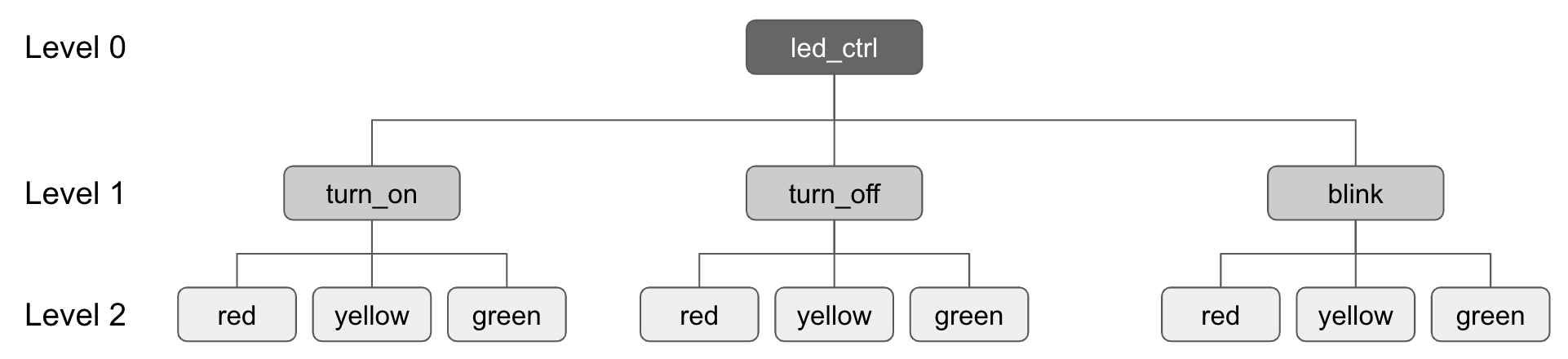
Level 0
The root (or level 0) command can be created with the following macro:
// Root level 0 command
SHELL_CMD_REGISTER(
  led_ctrl,
  &led_actions,
  "Command to change LED states.",
  NULL);
The first parameter specifies the syntax for the command, which is later available inside the Shell. The second parameter is the array of subcommands (level 1). In the third parameter, you provide helpful information, which is printed if the user uses the help subcommand. The unused fourth parameter is an optional callback function, fired once the command is run by the user.
Level 1
The first level of subcommands consists of the actions you can do with the LEDs: Turn on, turn off, and blink. The following macro creates a set of subcommands named led_actions:
// level 1 commands
SHELL_STATIC_SUBCMD_SET_CREATE(
    led_actions,
    SHELL_CMD(turn_on, &led_names, "Turn the LED on.", handle_turn_on),
    SHELL_CMD(turn_off, &led_names, "Turn the LED off.", handle_turn_off),
    SHELL_CMD(blink, &led_names, "Make the LED blink.", handle_blink),
    SHELL_SUBCMD_SET_END);
It consists of our three subcommands defined with the macro SHELL_CMD, where each needs to be provided with 4 parameters:
- a name (the name later used in the shell command)
- a pointer to the subcommands (level 2; our LED names)
- a helpful description
- a command handler function, called once the command is executed
The set must contain SHELL_SUBCMD_SET_END as the last member.
The command handlers for the subcommands can be specified in the following way:
// callback for the turn on subcommand
static int handle_turn_on(const struct shell* shell, size_t argc, char** argv) {
  for (int i = 1; i < argc; i++) {
    shell_print(shell, "Turning on %s LED.", argv[i]);
    set_led_state_by_color(LED_ON, argv[i]);
  }
  return 0;
}

// callback for the turn off subcommand
static int handle_turn_off(const struct shell* shell, size_t argc,
                           char** argv) {
  for (int i = 1; i < argc; i++) {
    shell_print(shell, "Turning off %s LED.", argv[i]);
    set_led_state_by_color(LED_OFF, argv[i]);
  }
  return 0;
}

// callback for the blink subcommand
static int handle_blink(const struct shell* shell, size_t argc, char** argv) {
  for (int i = 1; i < argc; i++) {
    shell_print(shell, "Blinking %s LED.", argv[i]);
    set_led_state_by_color(LED_BLINKING, argv[i]);
  }
  return 0;
}
The first argument is a pointer to the used shell instance. The second parameter is the argument count (the level 1 and 2 commands in this case). And the third parameter is a pointer to the actual arguments.
For example for the following command:
uart:~$ led_ctrl turn_off red
The values are:
| argc | 2 |
| argv[0] | turn_off |
| argv[1] | red |
And for:
uart:~$ led_ctrl blink red green yellow
The values are:
| argc | 4 |
| argv[0] | blink |
| argv[1] | red |
| argv[2] | green |
| argv[3] | yellow |
The first argument (argv[0]) is of no interest because we already linked the correct subcommands to the respective command handlers. We need to loop through the arguments >=1, which contain our level 2 subcommands.
Depending on the subcommand used, the callbacks simply call the following function with the appropriate target state to set:
static void set_led_state_by_color(enum LED_STATE state, char* led_color) {
  if (strcmp(led_color, "red") == 0) {
    led_red.target_state = state;
  } else if (strcmp(led_color, "yellow") == 0) {
    led_yellow.target_state = state;
  } else if (strcmp(led_color, "green") == 0) {
    led_green.target_state = state;
  }
}
Level 2
The last missing pieces are our level 2 subcommands (the names of the LEDs). The following macro creates them:
// level 2 commands
SHELL_STATIC_SUBCMD_SET_CREATE(led_names,
                               SHELL_CMD(red, NULL, "Red LED.", NULL),
                               SHELL_CMD(yellow, NULL, "Yellow LED.", NULL),
                               SHELL_CMD(green, NULL, "Green LED.", NULL),
                               SHELL_SUBCMD_SET_END);
The logic for creating the set is the same as with the level 1 subcommands. The only difference is that here we don’t provide command handlers. We already implemented all the needed logic in the level 1 command handlers.
That is all you need! Try it out now, and test if everything works as you expect it.
One last tip: If you want to control all LEDs at the same time, you can use an asterisk:
uart:~$ led_ctrl turn_off *
Turning off red LED.
Turning off yellow LED.
Turning off green LED.
uart:~$
Summary
In this blog post, we took a look at Zephy’s Shell, one of the most useful features for debugging and maintenance. We checked out built-in commands and implemented a custom shell command for controlling a traffic light. I hope you found this blog post useful. If you have any questions, please let me know! Stay tuned for the next one!