A Minimal ESP32-based Circuit
Have you ever wondered what it takes to make a custom PCB with an ESP32? Did you consider adding it to your design, but you didn’t know what parts were necessary? In this blog post, I will show you how to design a minimal circuit around the ESP32.
Shopping List
For the most basic ESP32-based PCB you will need:
- ESP32-Pico-D4
- 10uF Capacitor
- 0.1uF Capacitor
- 6x1 Header
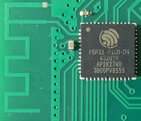
The easiest ESP32 to integrate into a custom PCB is the ESP32-Pico-D4. This chip is a so-called system-in-package (SiP). What does that mean? A SiP packs multiple chips and their peripheral (resistors, capacitors, memory, etc.) into one convenient package. The ESP32-Pico-D4 packs an ESP32 chip, 4MB of flash memory, a crystal oscillator, and a matching network for the external antenna. You can find an overview of all the components in the datasheet.
Besides the ESP32-Pico-D4 you only need two capacitors and six header pins. The capacitors are for compensating tiny disruptions of power. The headers are for you to connect your programming hardware and an external power supply.
Schematics
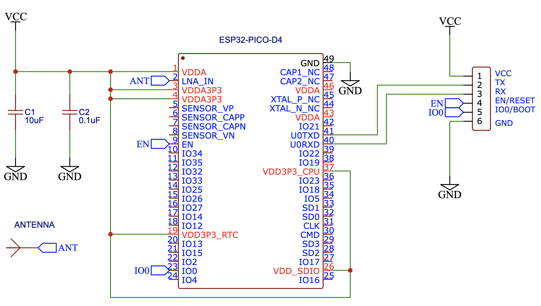
Getting the ESP32-Pico-D4 to run is surprisingly simple: You need to connect 3.3V (VCC) to the proper input pins (1, 3, 4, 37, [Optional: 19, 26]) and ground (GND) to the plane on the bottom of the chip. The best way to connect GND is to create multiple vias below the chip, which also helps with thermal conduction. If you now apply 3.3V to pin 9 (EN), the ESP32 will boot up.
How to Programm your Board
Congratulations, you just booted up your ESP32! Great! But how do we program it? First, you need to bring the ESP32 into bootloader mode: Connect pin 23 (IO0) to GND while connecting pin 9 (EN) to VCC.
Now you can upload your program to your EPS32 via UART (pins 41/TX and 40/RX). You can do this using a TTL adapter, a simple USB device that translates between your PC and the ESP32. Don’t forget to disconnect pin 23 (IO0) from GND after the upload. You can reboot by connecting pin 9 (EN) to GND and then to VCC again.
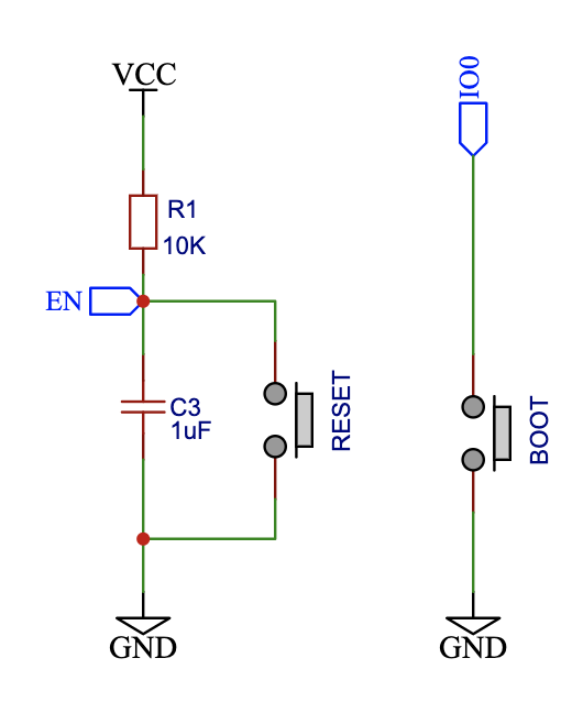
After flashing a couple of times using this process, you will regret not adding buttons to your board. Please, do yourself a favor and add two buttons: One for rebooting/resetting and one for the bootloader mode. Both buttons simply connect the respective pin to GND. For pin 9 (EN) you will also need a pull-up resistor (R1, e.g.: 10K) and a capacitor (C3, e.g.: 1uF), to pull the pin to VCC if the button is not pressed:
Antenna
Some people consider antennas black magic. I cannot teach you how to make an antenna in this post. Designing an antenna involves engineering a matching circuit, simulations, prototyping, certifications, and much more. It is an expensive and iterative process. If you don’t know what you do, you can create an antenna that interferes with other wireless communications (your neighbor’s wifi).
A quick and dirty approach would be to copy an existing design as closely as possible. Here is a PCB trace-based antenna I often use:
You can import it into your favorite PCB design software and connect it to pin 2 of the ESP32. The SiP already contains a matching network, which seems to work well enough with this antenna. Make sure to adjust the trace width between the pin and the antenna, so the impedance is approximately 50 Ohms. You will need information from your PCB manufacturer for this (they often provide an online calculator).
Summary
In this blog post, I showed you how to create a minimal circuit around on the ESP32-Pico-D4. Please, use the schematic as a rough guideline and adapt it to your own needs. The text is kept short intentionally, it is only meant as a kick-starter for your own research!